
















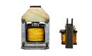

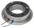



Design of device magnetic circuit
In magnetic devices, problems usually appear only when it is too late for an inexpensive fix. The prototype may hold, switch, or separate correctly, but in real operation it overheats, loses efficiency, or fails to achieve the required force. That is why designing a magnetic circuit is much more than simply choosing a magnet or a coil. It determines whether the result will be technically stable, manufacturable, and economically viable.
Industrial practice shows that a magnetic circuit must be viewed as a complete system. It includes the source of the magnetic field, the conductive flux path, air gaps, the working area, and the surrounding materials. If only one element is considered, for example the strength of a permanent magnet according to a catalog value, the result is often misleading. Catalog parameters are measured under defined conditions, not inside a specific machine, separator, clamping system, or electromagnet.

What Determines the Design of a Device’s Magnetic Circuit
The foundation is understanding what function the circuit is supposed to perform. A lifting magnet has different requirements than a magnetic separator, and both differ from a precision sensor or locking mechanism. In one application, maximum holding force is critical; in another, field homogeneity, switching speed, or minimal remanence after demagnetization matters more.
That is why the design process does not begin with the material, but with the operating conditions. It is necessary to know the working distance, the type of contact surface, gap tolerances, temperature, load dynamics, and surrounding materials. The difference between an ideally machined steel surface and a real component with scale, paint, or unevenness is often significant. In practice, the limiting factor is frequently not the magnet itself, but the air gap, which can dramatically reduce the effectiveness of the entire circuit.
The choice of operating mode is also important. If the device operates continuously, thermal stability and loss reduction become priorities. If the application involves short impulse operation, the design can move closer to the material limits. What works in a laboratory test for a few seconds may fail in continuous industrial operation.
Core Material and Its Limits
In ferromagnetic parts of the circuit, the difference between “magnetic steel” and a suitable engineering material for a specific task is often underestimated. Not every steel component conducts magnetic flux equally well. Permeability, saturation, hysteresis losses, and machining methods all play an important role.
In static applications using permanent magnets, the goal is usually to close the magnetic flux path as efficiently as possible while minimizing leakage. With electromagnets, alternating or pulsed effects must also be considered. If the core is repeatedly magnetized and demagnetized, eddy currents and hysteresis losses become relevant. At that point, the design challenge is no longer just about force, but also heating and efficiency.
The core material must have a sufficient cross-section. If it is too small, magnetic saturation occurs, and further increases in magnetomotive force will no longer produce the expected increase in flux. This phenomenon is a common reason why an electromagnet does not increase its force proportionally after the current is raised, even though a designer may intuitively expect it to.
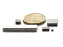
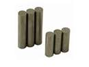
With permanent magnets, selecting the magnet material is a separate topic. Neodymium magnets offer high energy density but are more sensitive to temperature and corrosion. SmCo handles higher temperatures and more aggressive environments, though at a higher cost. Ferrite is economical and stable but bulkier at the same performance level. AlNiCo remains useful where thermal resistance and specific demagnetization characteristics are important. The correct choice therefore depends on the entire application, not on a single catalog value.
Why the Air Gap Is Often Critical
Magnetic flux does not follow the “best” path according to the designer’s intention, but according to physics. Air has very high magnetic resistance compared to ferromagnetic material. Even a small air gap can therefore reduce induction enough for the device to lose its functional reserve.
This applies to clamping, separation, and position sensing alike. Paint, dirt, uneven surfaces, vibrations, or manufacturing tolerances may create a gap that was never present in the drawing. A well-designed magnetic circuit therefore accounts for real operating conditions and does not rely on zero reserve simply because the model “barely passed.”
Circuit Geometry Is Not a Detail
The shape of pole pieces, flux direction, contact area, and closure of the magnetic circuit directly affect both the resulting force and the field characteristics. Two devices using the same magnet can behave very differently simply because the pole geometry is designed differently.
If the goal is high local force, concentrating the flux into a smaller area helps. However, if the area becomes too small, the material saturates and the effect stops increasing. If the objective is a uniform field across a larger space, the pole arrangement must be designed differently. This is typical in measurement and sensor applications, where maximum holding force is less important than repeatability and field shape.
Leakage flux must also be considered. It is not merely a theoretical loss. It can affect nearby components, electronics, sensors, or attract unwanted ferromagnetic particles outside the working zone. In separation technology this is especially important, because a seemingly strong field does not automatically mean efficient collection where it is actually needed.
Calculations, Simulations, and Real Operating Conditions
Today, accurate magnetic circuit design is difficult without calculations. Basic analytical equations help estimate flux, induction, force, or required excitation, but they reach their limits with more complex geometries. That is why numerical simulations are increasingly used to show field distribution, local saturation, and sensitivity to gap changes.
However, simulation is not a substitute for engineering judgment. The output is only as good as the input data. If the model ignores tolerances, welds, surface layers, assembly inaccuracies, or the real B-H characteristics of the material, the results may look convincing while still being misleading.
In practice, the most reliable process is to begin with requirements, continue with preliminary calculations, then simulation, and finally physical validation. Especially in industrial equipment, a prototype is essential. Only real measurements reveal whether the system behaves the same under heating, contamination, cyclic loading, and with the actual material it will process.
Where Designs Most Commonly Fail
The problem is usually not that the magnet itself is too weak. More often, the task has been defined incorrectly. A designer assumes perfect contact, but in operation there is a millimeter of dirt between the pole and the workpiece. Or a strong neodymium magnet is selected without considering operating temperature, causing the device to lose performance over time. In another case, the core may appear mechanically robust but becomes magnetically saturated before reaching the required force.
Failures also occur when maintenance and servicing are underestimated. If the magnetic system becomes contaminated with metal dust, the working gap and flux change. If the device is disassemblable, every joint and tolerance affects the result. A good solution therefore must work not only immediately after assembly, but also after hundreds of cycles and normal wear.
Magnetic Circuit Design in Practice
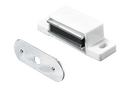
In industry, magnetic circuits are rarely designed as an isolated discipline. They are part of mechanics, electrical systems, safety, and manufacturing technology. That means the optimal solution is usually not the one with the highest induction, but the one that works best as a complete system.
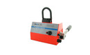
In lifting applications, safety margins and behavior during power failure are critical. In magnetic chucks, repeatability and force distribution across the workpiece play a major role. In separators, it is important where the field gradient is generated and how quickly the material moves. In electromagnets, cooling, coil insulation, duty cycle, and control requirements also become important.
That is why it makes sense to consult the design with a supplier who understands not only magnet materials, but also how they behave in real equipment. Experience from actual applications often reveals risks that do not appear critical in calculations. In engineering practice, the real value lies in understanding where additional power helps, where geometry should be modified, and where the entire operating principle should be changed instead.
If a magnetic circuit is expected to operate reliably, it is not enough to ask how strong the magnet should be. The more accurate question is what function the device must still perform when conditions are no longer ideal. That is where the quality of both the design and the technical partner behind it truly becomes visible.