















Frying magnet on CNC machine: when it pays off
If time is repeatedly lost during milling due to mechanical clamping, a CNC milling magnet is often one of the first ways to reduce setup time without compromising machining quality. However, this does not automatically apply to every part, material, or operation. In magnetic clamping, details matter – from material permeability and workpiece thickness to cutting force characteristics and contact surface geometry.

What a CNC milling magnet actually solves
In practice, it’s not just about the workpiece being held without a vise. The real benefit lies in accessing a larger portion of the part from a single clamping operation, reducing setup time, and improving repeatability. In series production, this means less handling time; in single-piece production, it simplifies positioning of more complex shapes.
Magnetic clamping also removes some mechanical obstacles from the workspace. The tool gains better access to edges and surfaces, which is especially important for finishing operations or when machining thinner plates. Another advantage is the reduced risk of local deformation that can occur with overly aggressive mechanical clamping.
That does not mean a magnet replaces all other clamping methods. Under high lateral forces, with small contact areas, or when working with non-ferromagnetic materials, mechanical or combined clamping still has its place.
When a CNC milling magnet makes the most sense
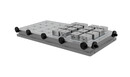
Magnetic clamping performs best with flat ferromagnetic parts where there is sufficient contact area and the workpiece has adequate thickness. Typical examples include steel plates, flanges, cut blanks, fixtures, or semi-finished parts that need to be machined from the top and around the perimeter.
It also works very well where parts change frequently and time matters. If an operator repeatedly loosens a vise, cleans contact surfaces, and repositions the workpiece every few minutes, a magnetic solution can significantly reduce this loss. In repeated series, the productivity difference can be substantial.
Another suitable application involves parts that might deform or get marked under mechanical clamping. A magnet distributes the clamping force across a larger surface. This is one reason it is used for finer machining of plates and thin-walled components, provided the material and cutting conditions allow it.
Where magnetic clamping has limits
A common misconception is that the maximum holding force stated in the specifications is all that matters. This value alone is not sufficient. In real operation, factors such as contact quality, flatness of the bottom surface, workpiece thickness, pole spacing, and load direction must be considered.
Problems arise with materials that have low magnetic permeability or with non-ferromagnetic metals such as aluminum, copper, or certain stainless steels. In such cases, the magnetic field cannot form a proper closed circuit, and clamping becomes weak or unusable. The same caution applies to parts with very small contact areas or interrupted contact.
The machining process itself can also be a limiting factor. Heavy roughing, aggressive side milling, or sudden changes in cutting direction generate forces that may not be suitable for standalone magnetic clamping. In such cases, a combination of a magnet with stops, side supports, or auxiliary fixtures is often used.
Permanent or electro-permanent system
Choosing the type of magnetic system is often a key decision. Permanent solutions are structurally simple, stable, and independent of continuous power supply. This is an advantage where reliable operation without complex installation is required.
Electro-permanent systems are interesting because they typically require electrical energy only when switching states. After activation or demagnetization, they hold without continuous power consumption. In CNC environments, this provides a good balance of safety, control, and integration capabilities. However, it is also a technically and financially more demanding solution.
The choice therefore depends on the type of production. For simpler workplaces, mechanically operated magnetic clamping may be sufficient. For more automated or demanding applications, systems with controlled switching, status monitoring, and precisely defined operating modes are often more suitable.
Which technical parameters to focus on
In CNC milling, it is not enough to look at marketing-friendly numbers. Important parameters include pole pitch, magnetic field depth, the recommended workpiece thickness range, and behavior when poles are only partially covered. These factors directly affect whether the magnet can hold a specific part reliably under real machining conditions.
Workpiece thickness is critical. If the part is too thin, the magnetic flux may not close efficiently, and holding force decreases. Conversely, results are significantly better with thicker steel parts. That is why it is always necessary to assess the specific combination of material, dimensions, and contact area, not just general compatibility with steel.
Surface quality also matters. Scale, dirt, chips, or unevenness create an air gap that reduces holding force. In magnetic clamping, surface cleanliness is a functional requirement, not just an operational detail.
Accuracy, vibrations, and surface quality
A properly selected CNC milling magnet improves tool accessibility, but machining accuracy depends on the entire setup. If the workpiece is not properly supported or begins to vibrate during cutting, this will affect both dimensions and surface quality. The magnet alone does not eliminate vibrations.
For thin parts, it is often necessary to use support plates, pole extensions, or technological bridges to ensure even support. For more complex shapes, auxiliary stops can help prevent lateral movement without taking over vertical load.
If magnetic clamping is designed correctly, the result is often a more stable process than improvised mechanical clamping. If part geometry or force direction is underestimated, the benefit of fast setup is quickly offset by the risk of workpiece movement.
When to choose combined clamping
In many operations, the choice is not strictly magnet or vise. A combined approach is often more practical. The magnet provides base surface clamping, while mechanical elements ensure positioning, orientation, or resistance to lateral movement.
This approach is particularly suitable for irregular shapes, interrupted cuts, or situations requiring more aggressive milling while maintaining access to most surfaces. Combined solutions also reduce the need for excessive holding force reserves, as different elements share functions.
For engineers or technologists, this is often the most practical path. Instead of searching for a universal clamping solution, the system is designed based on the specific part, machine, and production cycle.
How to approach selection for a specific operation
For magnetic clamping to work reliably, selection must be based on real production conditions. The first step is defining the material and minimum workpiece thickness. The second is evaluating the type of operations—face milling, peripheral milling, finishing, or roughing.
Next comes analysis of contact area and the direction of primary forces. With full contact of a steel plate, a magnet can be highly effective. With small segments or cut-out parts, the situation changes. It is then necessary to verify how many poles are actually active and whether weak points will occur.
The issue of operation and service is also critical. In industrial environments, the solution must be not only functional but also sustainable over time. Expert consultation in clamping design is often more valuable than catalog parameters. That is why, in more demanding applications, it pays to work with a technical supplier who can assess the entire process, not just sell a component.
Companies like SELOS Magnety are especially relevant in such cases, where customers need to connect product selection with technical validation, service, and real availability of the solution.
Most common mistakes when introducing magnets into CNC production
One of the most common mistakes is underestimating the testing phase. Magnetic clamping should be tested on actual parts and cutting conditions, not just adopted from a datasheet. The difference between theoretical and real holding force can be significant.
Another issue is poor surface cleanliness and incorrect workpiece positioning. Even a high-quality system loses effectiveness if chips are present between poles or if the part does not sit fully flat. A third common mistake is relying too much on the magnet without lateral stops where cutting forces act primarily horizontally.
If these points are addressed early, magnetic clamping can deliver significant time savings and better workplace organization. Not as a universal solution, but as a precisely chosen tool for a specific type of production.
In CNC milling, the most effective solutions are those aligned with the real process, not just paper specifications. That is why it makes sense to evaluate the magnet based on the part, machine, and machining method—only then does it become clear whether it is a good investment or a compromise that won’t pay off in operation.